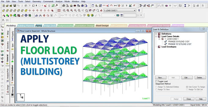
Staad Pro Method to Apply Floor Loads to Slab Panel
To be honest, it is more accurate to use the manual calculation for load calculation. But when you are working on Staad Pro, you are well-suited to apply floor loads to slab panel. But the method of doing this can be a little bit confusing. So, today we will discuss how to apply floor loads to slab panel in Staad Pro.
When you direct Staad Pro to apply floor loads to a slab panel, the software will use an advanced computational method to determine the equivalent load and apply it to the beams. This way, you are spared from the hassle of calculating all that by hand. While this method is fast, due to the proprietary computational algorithm the calculation results may be a little bit different from the manual calculations.
Considerations before calculating the floor load transfer in Staad Pro
As the program calculates the tributary load for the slab and beams, it also takes into consideration the appropriate self-loads of the members themselves. Staad Pro makes the following assumptions while calculating the floor to slab load transfer:
1. The slab in question is a two way slab.
2. The member load is a linear variation load, or a load that is linearly varying. The start and end values of the load may be of different magnitude.
3. The floor load is coming from a basic entity ? a plate, solid, or curved surface, which is not part of the structural model, and is acting as the medium for the application of this load.
Additionally, we cannot declare these loads on the following member types:
1. MEMBER CABLE
2. MEMBER TRUSS
3. MEMBER TENSION
4. MEMBER COMPRESSION
5. CURVED
General Format for assigning load transfer from floor to slab in Staad Pro
We have given:
1. f1, f2: global coordinate values specifying location in Y, X & Z ranges respectively.
2. The above specifies the plane on which the load-bearing members are present. Loads are calculated for these members only.
3. f3: load value expressed in unit weight over square length.
a. When command begins with YRA, then this load acts parallel to the positive global Y. Load is projected on plane X-Z.
b. Similarly, if you begin the command with XRA, then this load acts parallel to the positive global X. Load is projected on Y-Z plane.
c. Similar rules apply for ZRA starting commands as well ? load falls on X-Y plane and acts parallel to the global positive Z.
4. F4, f5, f6, f7: the four corner points defining the area on which the load is supposed to act. They are expressed as global coordinates.
5. GX, GY, GZ: global directions towards which the load should be redirected. This should act in magnitude of the load basing on the area projected on the plane, when global direction was not mentioned. These options are very useful when you want to calculate mass.
6. INCLINED: When your floor panel is inclined, this value denotes the inclination of the panel that a set of members form, in respect to the global planes XY, XZ, or YZ.
Respecting the above, the command format should be as follows:
FLOOR LOAD {
1. YRANGE f1 f2 FLOAD f3 (XRA f4 f5 ZRA f6 f7) { GX | GY | GZ } (INCLINED)
2. YRANGE f1 f2 FLOAD f3 (XRA f4 f5 ZRA f6 f7) { GX | GY | GZ } (INCLINED)
3. YRANGE f1 f2 FLOAD f3 (XRA f4 f5 ZRA f6 f7) { GX | GY | GZ } (INCLINED)
4. _FloorGroupName FLOAD f3 { GX | GY | GZ } (INCLINED)
}
For example: FLOOR LOAD { YRA 11.9 12.1 FLOAD -0.25 XRA 0.0 11.0 ZRA 0.0 16.0 }
Points to remember when using the above method of using Staad Pro for floor loads
1. The floor panel is assumed to be uniform, contiguous and without holes. The load is assumed to not vary with length of any side.
2. If the panel is not square or rectangular:
a. Calculate the CG of the polygonal area of the floor.
b. Each corner of the CG is connected to form triangles.
c. Draw a vertical line from the CG to the other side of each and every triangle.
d. For each triangle: if the intersection of the vertical and the side to which it was drawn to falls outside of the tringle, then the uniform load of that triangular area will be calculated and added to the total load.
e. If the point of intersection is inside or on the side of the triangle, a triangular load will be calculated.
Make sure you check the GA drawing, the north direction, scale, units, grid dimensions, story heights, orphan nodes, zero length lines etc. to make sure your model is error free before you embark onto these calculations. Otherwise, you may be facing some nasty surprises!