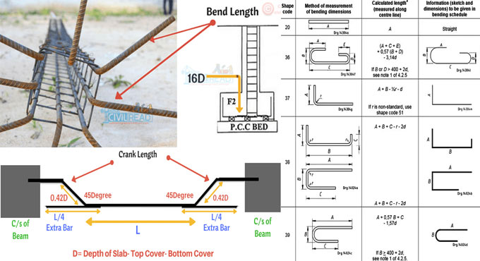
Some useful tips to work out the length of the bent bars

While fabricating reinforcing bars with bends, the straight bar is primarily cut to a length that is under the sum of the specified dimensions of the bent bar.
The variation among the detailed length and the cut length belongs to the ?bend curvature deduction? and called as various names like gain, creep, and gyp. Usually, the fabricators and programmers get the bend curvature deduction from a bend deduction table.
In the following table 1, the deductions for 45- and 90-degree bends of common bar sizes are provided.
Figure 1 illustrates a No. 8 (No. 25) bar with a standard hook and sides estimating 1 ft 4 in. and 4 ft (400 and 1220 mm). The detailed length of this bar is obtained by summing up the two sides, or 5 ft 4 in. (1620 mm). From Table 1, the deduction for a 90-degree bend on a No. 8 (No. 25) bar is 2-1/2 in. (65 mm). So, in such a case, the cut length of the bar should be 5 ft 1-1/2 in. (1555 mm).
The usual standard for working out the cut length of a bar is along the actual centerline of the bar, that is equivalent to the neutral axis of the bar cross section before bending. The cut length of a bent bar is less than the sum of the finished dimensions due to the following reasons :-
The fillets formed at the bend points contain an arc length that is lesser than the sum of the intersecting tangents. This component of the bend deduction is obtained with a easy-to-follow mathematical calculation.
If the exterior fibers of the bar are elongated easily, the inner fibers of the bar are constrained by friction against the bending mandrel, so, the neutral axis shifts inward approaching the mandrel. It is critical to measure this component. The inconsistency arises from computing the lengths on the basis of the actual centerline is not very important.
While detailing the reinforcing for a large precast segmental bridge, it was found that there were over 200 different bar shapes, of which most were multi-sided, closed stirrups containing diverse angles. It is required that the cut length of the bars should be within a tolerance of 10 mm (3/8 in.), irrespective of the number of bends on the bar or the angles. It can?t be done with a chart. The capability to work out the perfect bend deduction for each bend at any angle on each bar size should be introduced into the detailing software.
To resolve this, the calculations should contain a term that would facilitate the effective centerline of the bend to move inward from the actual centerline.
One way to contain this effect in the arc length calculations is to apply an effective centerline situated at a distance ?(db/2) from the inside of the bend, where ? denotes a variable labeled the friction factor. With zero friction, ? = 1 and the effective centerline is situated at the actual centerline. With zero slip, ? = 0 and the effective centerline is situated at the inside face of the bend.
For a specified bar size and mandrel, a calibration for the ? value is created by cautiously working out the lengths of straight bars, bending them to the same angle, computing and summing the dimensions of the two resulting sides, subtracting the original straight length from this sum to determine the total bend curvature deduction, and solving the equations provided.
Several factors along with bar size, steel grade, angle of the rib to the mandrel, the mandrel material, the amount of wear on the mandrel, the bending speed, and the bar temperature (the shop performed through winter and summer), were set up to impact the value of ?. Suppose, there are four bending machines in the shop, and each one is alloted a value for ? for each bar size. Bending speed is fixed at a constant prescribed rate for each bender, and the entire process is reexamined every couple of weeks. The 10 mm (3/8 in.) tolerance could be attained successfully, on condition that the client can efficiently manage the several factors influencing ?.
Unpredictably, the value of ? is normally about 0.2 to 0.25 and seldom approach 0.3. If the bending speed is raised, ? would fall to as low as 0.1. There exist a small amount of Grade 75 (520 MPa) bar on the project for which ? should be set to zero. It appears to indicate that friction with the mandrel is too high (because of the force necessary to bend the bar) that there is no slip along the inner curve and that all of the elongation is along the outside curve of the bar.


