Design of Reinforced Concrete T Beam
T beam bears the load of the whole structure of reinforced concrete. It is a T shaped cross section structure. The slab which is around the beam is called a flange.
Isolated Beams
In this kind of beam the flange is used to provide compression area the thickness of flange should be greater than 1/2bw, and width should be less than or equal to 4bw.
Internal T Beams
1. Fourth the clear span length of the beam, L/4.
2. Width of web plus 16 times slab thickness, bw +16hf.
3. Center-to-center spacing of the beams.
L Shaped Beam
1. Effective flange width should be equal to or smaller than (bw+(Clear span/4))
2. Effective flange width should be equal to or smaller than (bw+(6hf)
3. Effective flange width should be equal to or smaller than (bw+half clear distance to the next clear web beam)
Design Process
T section beam calculates the dimensions of the beam and the reinforcement area. The size of the beam web affects the size of the rectangular beam.
1. Calculate applied moment (Mu) using beam span and imposed loads.
2. Determine Effective Flange Width (be)
3. Choose the web dimensions (bw) and (h) based on either negative bending requirements at the supports, or shear requirements.
4. Assume, a=hf , then calculate (As) using the following expression:
5. Check the assumed value of (a):
6. In Equation 2, plug the value of (be) found in Step 2.
7. If a< hf, design the beam as a rectangular section and follow the design procedure of the rectangular beam.
8. If a> hf, design the beam a T-section and go to Step 6.
9. Compute the reinforcement area required to balance the moment of the flange use Equation 3, and then flange moment employ Equation 4:
10. Calculate moment of the web:
11. Assume a rectangular stress block depth (such as a= 100 mm), then estimate the amount of reinforcement area (Asw) required to balance the web moment:
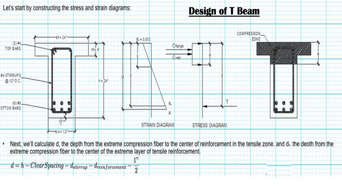
12. The value of (d) should be computed using the following formula:
13. d= beam height-concrete cover- stirrup diameter- 0.5*longitudinal steel diameter Equation 7
14. Then check assumed rectangular stress block depth (a) using (Asw):
15. Use the new (a) and plug it into Equation 6, then compute new (Asw). Repeat this process till correct (Asw) is reached. Commonly three trials are enough.
16. Compute total As which is equal to (Asf+Asw), then determine the number of reinforcement:
17. No. of Bars= As/ area of single bar Equation 9
18. sketch the final design on which all necessary data are represented.
Example of design process:
A floor system shown consists of a 75 mm concrete slab supported by concrete T-beams with a 7.5 m span and 1.2 m on centers. Web dimensions, which are determined by negative moments requirements at supports, are bw= 275 mm and d= 500 mm. What is the tensile steel area required at midspan to support a factored moment of 725 KN.m? Material properties: fc?= 21 MPa and fy= 420 MPa.
The Solution
1. Applied moment is provided, Mu= 725 KN.m
To get more details, go through the following video tutorial.
2. Find effective flange width should be, which is the smallest of the following:
Span/4= 7500/4= 1875 mm
bw +16hf= 275+16*75= 1475 mm
Center-to-center spacing of beams= 1200 mm
Therefore, the effective flange width is equal to 1200 mm.
3. Dimensions of the web are provided.
4. Let us say, a=hf= 75 mm, and assume a strength reduction factor is equal to 0.9.
As= (725*106)/(0.9*420(500-0.5*75)= 4147.004 mm2
5. Now you have to check the assumed value of (a), use (As) computed in Step 4:
a=(4147.004*420)/(0.85*21*1200)= 81.31 mm
Since a= 81.31 mm> hf=75 mm, so the beam needs to be designed as a T-section.
6. Compute (Asf) and flange moment:
Asf= (0.85*21*(1200-275)*1200)/420= 2946.23 mm2
phi*Mnf= 2946.23*420*(500-0.5*75)*10-6= 572.23 KN.m
7. Calculate moment of the web:
phi*Mnw=725-572.23= 209.54 KN.m
8. Estimate the amount of reinforcement area (Asw), assume a=100 mm and phi= 0.9. Asw= (209.54*106)/(0.9*420*(500-0.5*100)= 1231.86 mm2
check (a) using the above (Asw),
a=(1231.86*420)/(0.85*21*275)= 105.4 mm
Find new (Asw) use a= 105.4 mm
Asw= (209.54*106)/(0.9*420*(500-0.5*105.4)= 1239.29 mm2
Since the new Asw is very close to the previous one, therefore further trial is not needed.
Asw=1239.29 mm2
9. Compute total As which is equal to (Asf+Asw):
As= Asf+Asw= 2946.23+1239.29= 4180.29 mm2
The assumed strength reduction factor should be checked:
Now you have to Choose a single steel bar that leads to a reinforcement area that is considerably higher than the total area.
There are three bars with a diameter of 32 mm, and the corresponding reinforcement area is 2457 mm2
There are three bars with a diameter of 29 mm, and the corresponding reinforcement area is 1935 mm2
The total reinforcement area is equal to 4349 mm2; this is the answer to the question.
So, steel bars are arranged in two-layers and the distance between the two layers is 25 mm.
Check the strength reduction factor:
Since the compressive strength of concrete is smaller than 30 MPa, therefore B1=0.85
neutral axis depth (c)= a/B1= 105.4/0.85= 124 mm
dt: distance from the compression face of the beam to the center of the bottom layer of steel bars:
c/dt= 124/525= 0.236<0.375.
Therefore, the assumption is correct.