Benefits of I-Beams in Construction
Hot-rolled steel beam having I-shaped cross section, and tapered flanges closer than wide flanged beam is known as I-beam.
I Beam contains one vertical plane and two horizontal planes or flanges which develop 'I' or 'H' structure. The vertical plane withstands the shear stress , whereas horizontal planes withstand the bending movement. I Beam is majorly utilized in construction industry like construction of manufacturing plants, multi-story buildings etc.
I-beam is frequently applied as important support trusses, or the primary framework, in buildings. Steel I beams retain structure?s integrity with persistent strength and support. The extreme power of I beams minimizes the requirement for several support structures and as a result huge time and money is saved. The stability of the structure is improved considerably.
Some vital jargons of I-Beam:
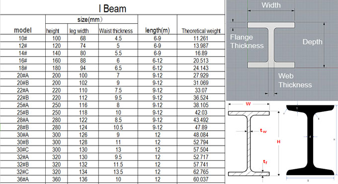
1. Flange thickness: Top and bottom horizontal plate-like segments of an I-beam are known as flange. The density of the flanges is defined as the flange thickness.
2. Flange width: The width of the flanges is known as flange width.
3. Beam depth: The height among the top and bottom surface of the steel I beam is termed as beam depth.
4. Web thickness: The vertical segment of steel I beam is known as web, and the thickness of the web is termed as web thickness.
5. Fillet radius: The curved section, where the changeover among the web and flange occurs is known as a fillet. The radius of the fillet is defined as the fillet radius.
A properly sized I Beam can be chosen on the basis of the following criterion:
The entire method of choosing the proper size of the I beam is dependent on the basic mechanical design calculations as given below:
1. The first input necessary belongs to the steel I beam load specifications or loading details on the steel I beam.
2. Draw bending moment diagram for the specified loads and get the value of maximum bending moments (suppose M) that the steel I beam is likely to experience.
3. Select an exact size of steel I beam from a standard I beam table.
4. Determine the area moment of inertia (suppose I) of the selected steel I beam.
5. Obtain the beam depth (suppose d) of the selected steel I beam.
6. The stress developed (f) in the beam can be measured with the formula given below :
f/(d/2)=M/ I
f denotes the bending stress.
M denotes the moment at the neutral axis.
y denotes the perpendicular distance to the neutral axis.
I denotes the area moment of inertia about the neutral axis x.
7. Compare the calculated value of the bending stress with the yield stress of the steel with the purpose of verifying the safety factor of your design.
The structural design will be perfect when the size of the I-beam is accurate. The method described above is dependent on static I beam load specifications. In case where dynamic loads are concerned, it is necessary to apply FEA tools like ANSYS, Pro Mechanica, etc.